Engineering
Simple Circuit Light
Build a real breadboard LED circuit with a resistor, jumper wires, and a small battery pack.
Medium · 45-60 minutes
Introduction
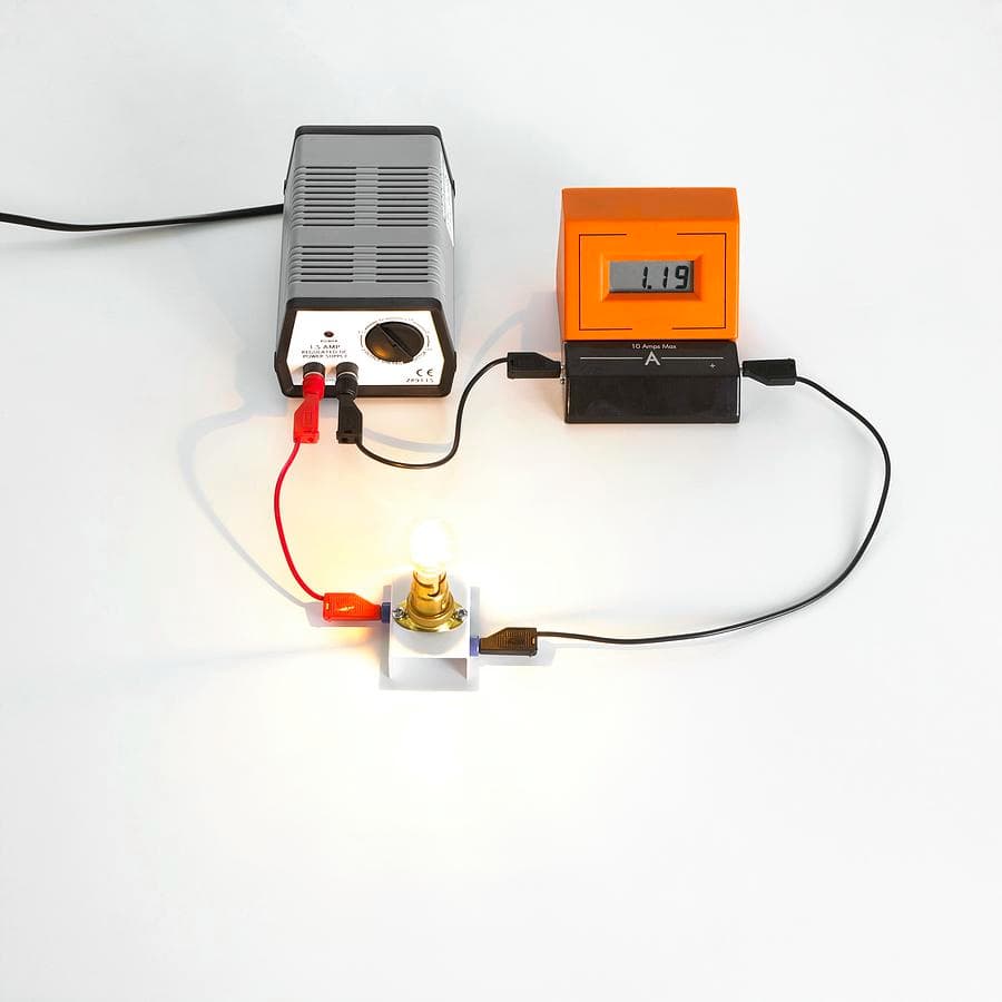
Flipping on a light feels ordinary, but inside that tiny click is a complete path for moving electric current.
In this project, you will build a beginner electronics circuit on a breadboard, which lets you connect parts without soldering.
You will also add a resistor in series with the LED. That resistor is important because it limits current so the LED does not burn out.
The Why
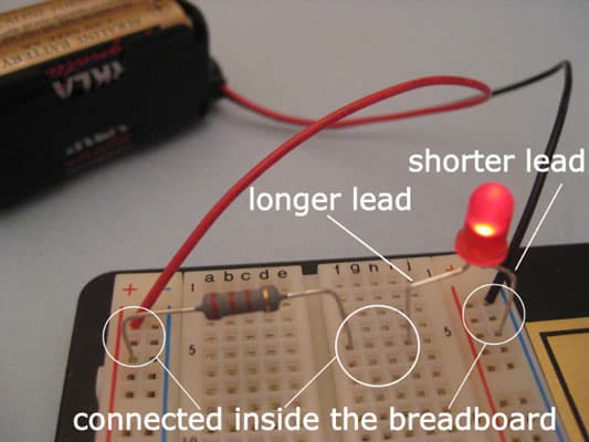
Current flows from the battery's positive side, through a jumper wire, through the resistor, into the LED's long leg, out the LED's short leg, and back to the battery's negative side. The resistor and LED are in series because the current must pass through one and then the other in the same loop. If the LED is backwards, current cannot flow through it correctly and it may not light.
Step-by-Step Instructions
- 1
Place the breadboard in front of you. Find the red positive rail (+), the blue negative rail (-), and the middle rows where parts plug in.
- 2
With the battery pack turned off or disconnected, plug the red battery lead into the + rail and the black battery lead into the - rail.
- 3
Put one end of the resistor into the + rail. Put the other end into an empty breadboard row, such as row 10.
- 4
Place the LED so the longer leg, called the anode, goes into the same row as the resistor end. Put the shorter leg, called the cathode, into a different row.
- 5
Use a jumper wire to connect the LED's short-leg row back to the - rail. Now the resistor and LED are in one series path.
- 6
Connect the battery or turn the battery pack on. The LED should light as current flows from +, through the resistor, through the LED, and back to -.
- 7
If the LED does not light, disconnect the battery first, then flip the LED around or check that each part is plugged into the correct row.

What each part does
- Battery pack
- The power source. Use a small battery pack, such as 2 AA batteries. The red lead connects to the positive rail and the black lead connects to the negative rail.
- Breadboard
- A solderless building board. Holes in the same row are connected inside, so you can join parts without twisting wires or using solder.
- Resistor
- A current limiter. It slows the flow of electricity enough to protect the LED from getting too much current and burning out.
- LED
- Light-emitting diode. It only works in one direction: the long leg is the anode and points toward positive, while the short leg is the cathode and points toward negative.
- Jumper wires
- Short insulated wires that connect breadboard rows to the power rails. They create the path current follows through the circuit.
Troubleshooting
| Problem | Fix |
|---|---|
| LED does not light | Disconnect the battery, flip the LED around, and check that the long leg points toward the resistor and positive rail. |
| LED lights but is very dim | Check for loose jumper wires and make sure the resistor and LED leg share the same breadboard row. |
| Nothing happens at all | Check the battery charge and confirm the red lead is on the + rail and the black lead is on the - rail. |
| LED gets hot or burns out | Disconnect the battery right away. The resistor may be missing, too small, or not actually in series with the LED. |